4
Fourth Build

I told myself there was NOT going to be a fourth build, but I lied. After putting most of it together, and breadboarding the MCU, I realized there were some issues. Some were enhancements I wanted to apply and some were mistakes I had to fix.
•
No longer using the ESP32, changed to Arduino Mega
•
The 6mm plastic sheet (see cross-section below) was replaced with a 2 mm aluminum sheet.
•
Magnet changed to stronger type (solenoid)
•
Stepper driver boards changed from A4988 to TMC2208: more current, quieter operation
•
Sensor board revamped, using both sides for components
Changes from 3rd build
NEW MCU
The ESP32 that I had planned in 3rd Build turned out to be a issue. There are 6 pins not available on the chip and I had already used all the remaining pins, which is never a good thing not to have spares.
The ESP32 did not have 5 volt tolerant input pins, requiring a voltage divider for each of the 5 inputs planned. Not a big issue, but it did take up board space. And what finally took the cake was the fact that not all input pins had pullup resistors (unlike the Mega below that has pullups on every pin).
I replaced the ESP32 with an Arduino Mega Clone. I had considered this guy before but it is so big, dimensions of a credit card, it would be hard to put on a printed circuit board and be able to put the other components on as well. I found a Mega clone that was 1/3 the size with all the pins available and totally compatible with the Mega 2560 firmware. It's closer in size to the ESP32 that I had been using. See images below. (hover for description)


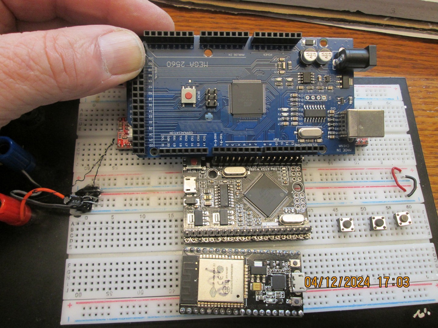
Photo showing relative sizes of MCU. Genuine Mega at top, Mega Clone in the middle, and ESP32 is at bottom.
NEW PCB
A new MCU necessitates a new printed circuit board to put it on. This is my latest design. Click to get scalable image
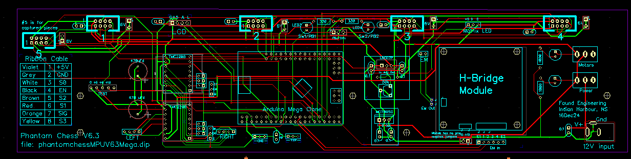
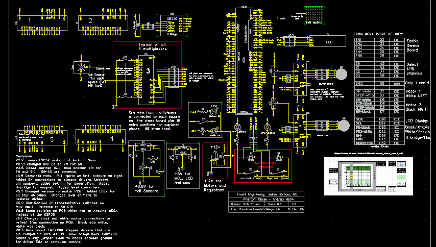
The schematic changed as well. Click for larger scalable image
NEW Stepper motor drivers
I was using the old standby A4988 for my stepper motor drivers and found them to be satisfactory. However, my friend in Argentina who is building one these things too said he swapped his out for TMC2208 which he said were quieter. Wow! Big difference in noise level and the 2208 have more drive current.
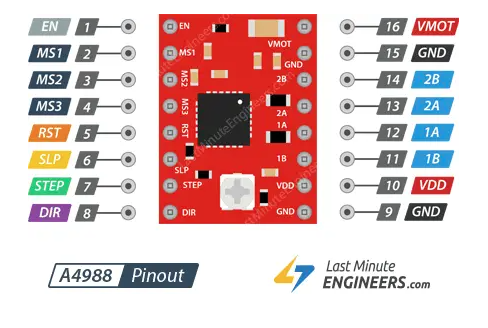
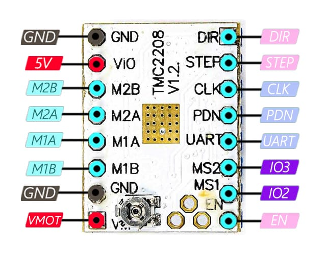
The TMC2208 (right) is pin compatible with the A4988 despite slightly different pins. Where they don't match, it doesn't matter. The TMC2208 has a UART input for total control, diagnostics, and information but it is not used in this case so I'm using the 2208 in "legacy-mode". Note that image of the 2208 is upside down compared to the A4988. (Maybe mine are knock-offs!)
NEW Hall sensor boards
II installed the Hall sensors on one side of the board and I also put the multiplexers and IDC connector on the same side. In other words all the components were on the COMPONENT side.
This was wrong and the reason it is wrong is because the entire sensor array of 64 devices will be sandwiched between two pieces of acrylic plastic and so must all be at the same distance above the board, about 2 mm.
The multiplexer in it's socket and the IDC connector are much higher and thus cannot be in the same "sandwich". By putting these on the OTHER side of the board, they can hang down in the slot of the bottom acrylic piece, as I had originally designed it.
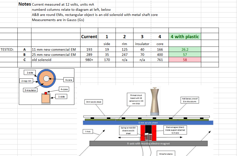
This drawing shows the sensors between the acrylic sheets. The image shows acrylic sheet over the electromagnet - this has been changed to 2mm aluminum sheet, proven better for increased magnetism.
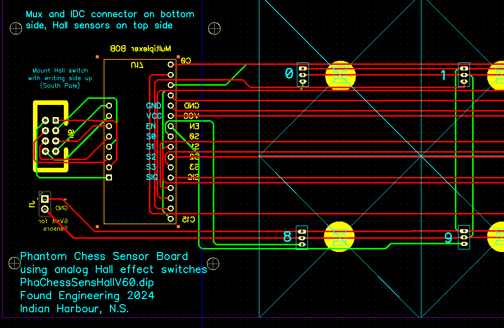
Above is the relevant section of the board that had to change. The IDC connector and the mux socket are shown in yellow since that is the opposite (bottom) side of the board. Putting these components on the other side was not as simple as it appears because the pins were all reversed, so I had to redraw the entire board. I also added a screw terminal for the 6V power and ground being fed only to the sensors. The mux chip uses 5 volts, provided through the IDC connector.
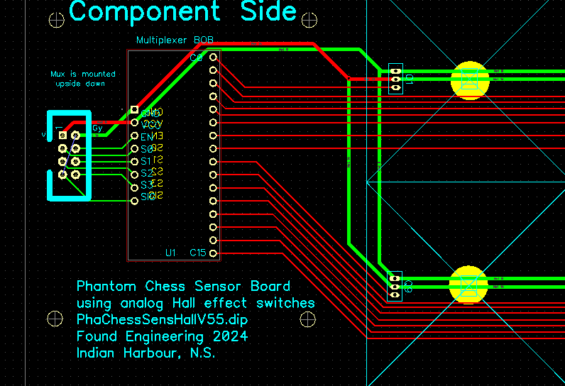
Compare the NEW V6.0 board above with the previous V5.5 where the IDC and mux were on the top side of the board
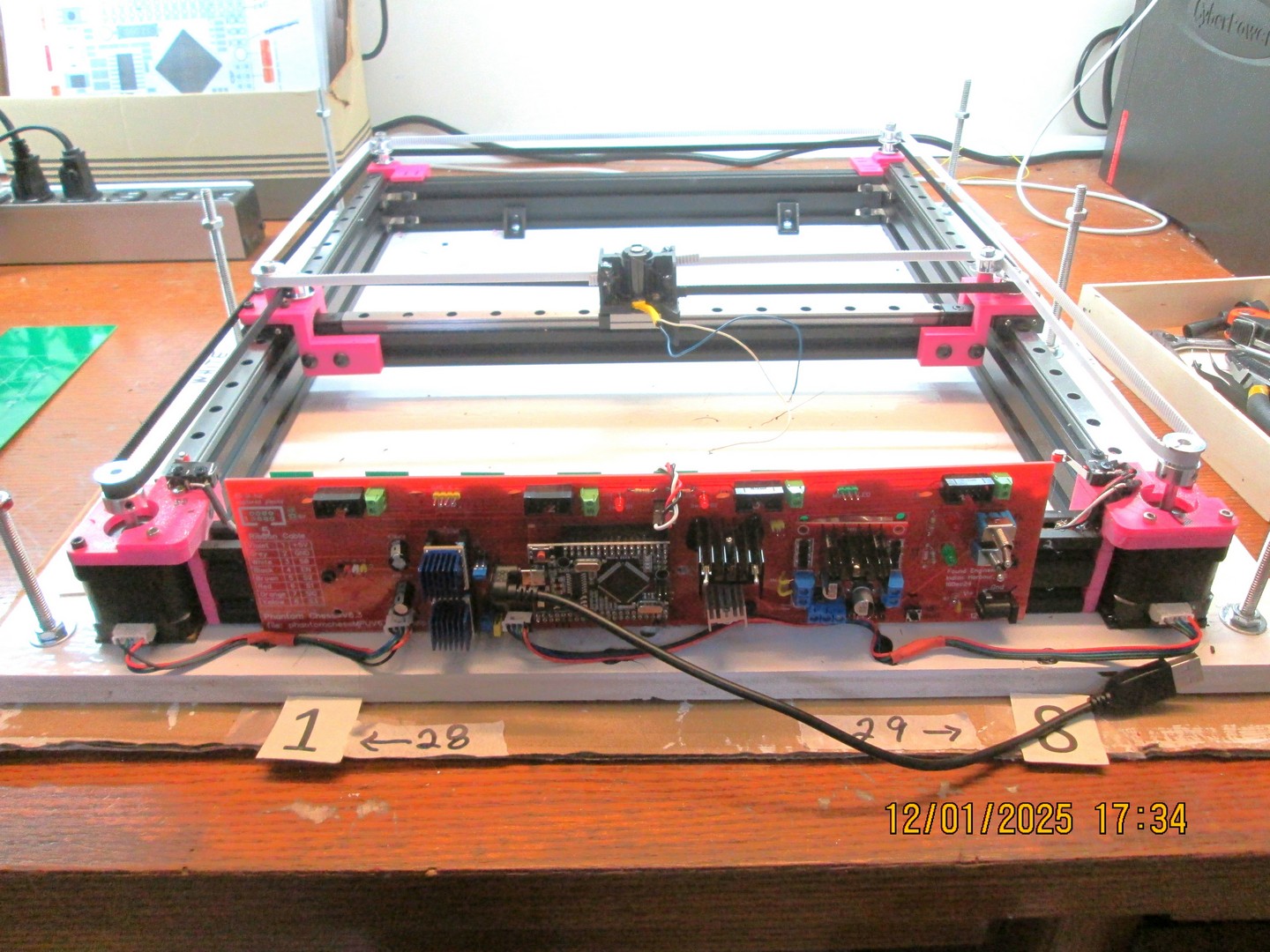
Update 13Jan2025
Arduino Mega PCB installed and working, all is ready for calibration to make sure EM (center) moves exactly 40mm, the size of a square. The newly designed EM holder has a solenoid for magnet and there is a light spring underneath it to keep it in contact with the board above it (not shown).
- Made holder for 20x4 LCD display
- Made and installed belt tensioner at far end of layout
- All calibrations (XY, Diagonal, and Start) completed
- Tested aluminum plate over electromagnet. This worked very well, but with addition of sensor board and top acrylic sheet, it did not work: not enough flux.
- Made electromagnet with AWG 38 copper wire, 3d printed spool. Specs not great (less than solenoid I was using) but it works. See photo below
- Added calibration switches to main board (drilled holes, glued switches into place.
Update 23Jan2025
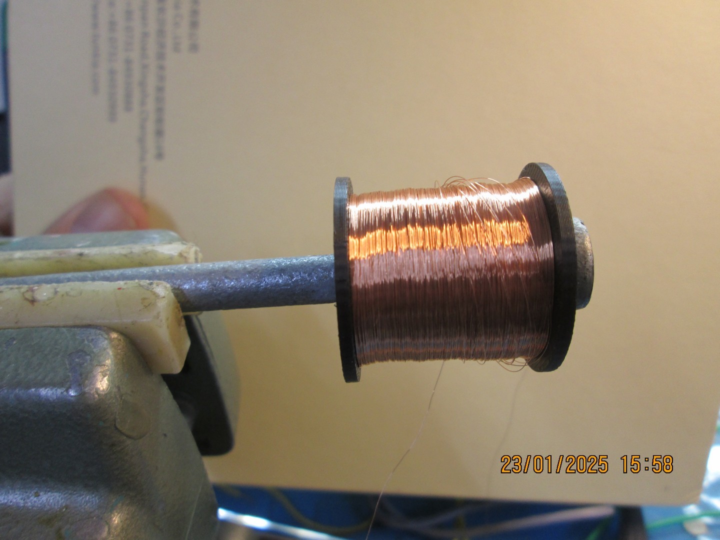
666 m of wire, 1600 ohms, 271 Gauss